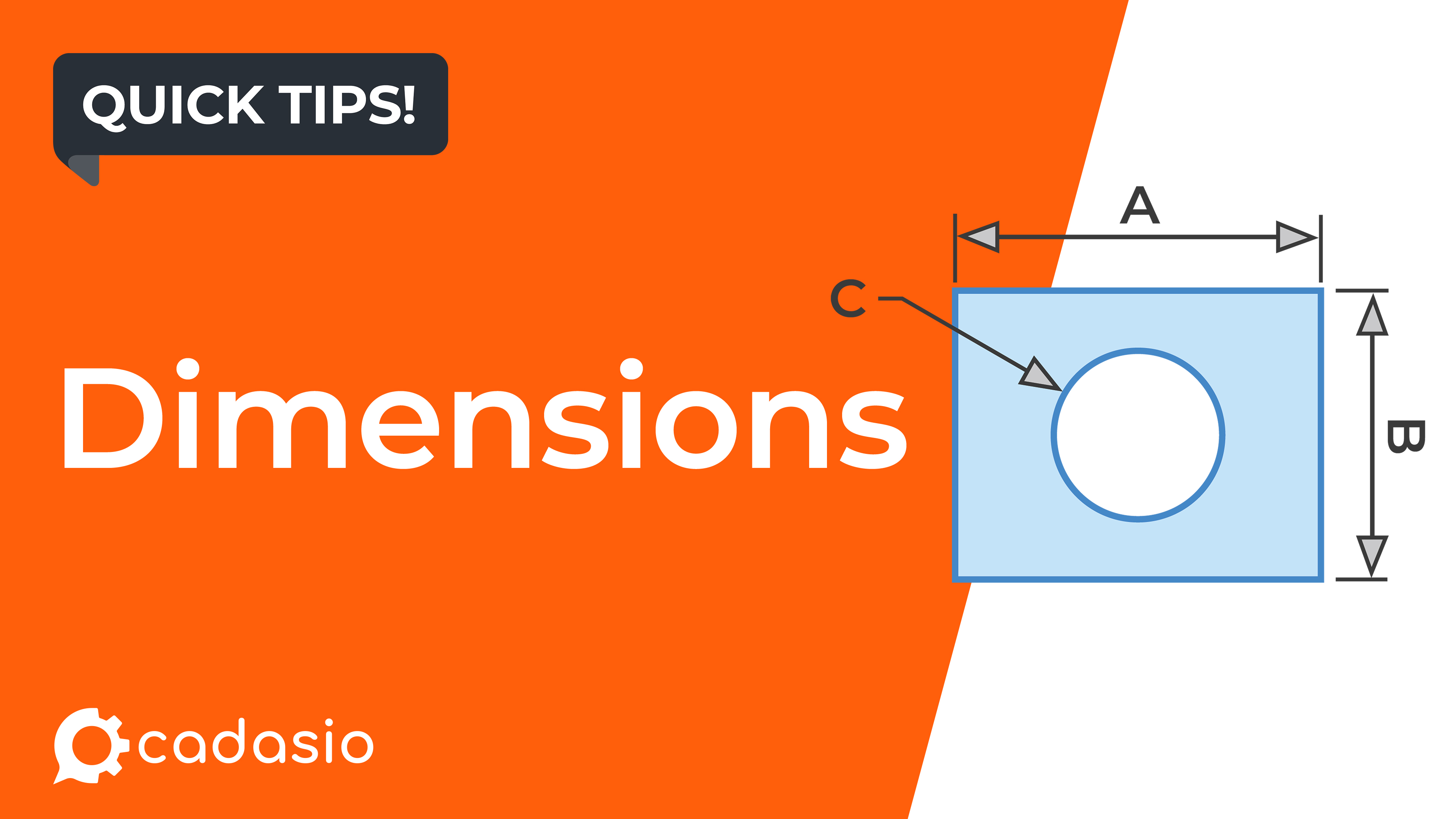
Whether you're creating assembly instructions, inspection documentation, or technical training content, dimensions can help provide additional context without requiring viewers to refer to external drawings.
In this article, we'll look at the different ways dimensions can be created and the options available to customise their appearance.
Getting Started
The Dimension tool is available in the standard Cadasio toolbox.
Once activated, dimensions are created simply by selecting geometry directly on the model. Cadasio automatically recognises what has been selected and creates the appropriate dimension type, allowing measurements to be added quickly without changing tools.
Depending on your selection, dimensions can represent lengths, distances, angles, diameters, radii, or centre-to-centre measurements.
Creating Point-to-Point Dimensions
The most flexible way to create a dimension is by selecting any two points on your model.
After selecting the first point, simply choose a second point and Cadasio creates a straight dimension between them.
This approach is particularly useful when measuring distances that aren't represented by existing model edges, such as the spacing between two features or reference locations.
For greater precision, hold Ctrl while selecting to snap directly to nearby edges, making accurate placement quick and straightforward.
Measuring Edge Lengths
When you select a single straight edge, Cadasio automatically creates a dimension showing the length of that edge.
This is one of the fastest ways to communicate the size of a component or feature and is ideal for highlighting cut lengths, extrusion sizes, bracket dimensions, or other important linear measurements.
Because the dimension is generated directly from the model geometry, there is no need to manually identify start and end points.
Measuring the Distance Between Edges
Selecting two parallel straight edges creates a distance dimension between them.
This is particularly useful when documenting:
- Required clearances
- Component spacing
- Installation gaps
- Assembly tolerances
- Relative positioning of parts
Displaying these measurements directly within the interactive model helps users understand exactly which features the measurement relates to, reducing ambiguity that can sometimes occur in traditional 2D drawings.
Creating Angular Dimensions
If two straight edges are selected that are not parallel, Cadasio automatically creates an angular dimension.
Angular measurements are commonly used to communicate:
- Assembly positions
- Bracket angles
- Bend angles
- Orientation requirements
- Component alignment
Because the angle is displayed directly within the 3D scene, viewers can immediately understand both the measurement and the geometry it relates to.
Working with Circular Geometry
Circular features are handled automatically.
Selecting a single circular edge creates a diameter dimension, while selecting a second circular edge creates a centre-to-centre measurement between both circles.
These measurement types are particularly valuable when documenting:
- Hole diameters
- Shaft sizes
- Mounting hole spacing
- Bolt patterns
- Bearing locations
Rather than relying on accompanying engineering drawings, these measurements remain visible directly on the interactive model.
Customising Dimension Appearance
Once a dimension has been placed, Cadasio provides a range of options for adjusting both its appearance and position.
Dimensions can be repositioned using the built-in triad controls, allowing measurements to be placed where they remain visible without obscuring important parts of the model.
Visual styling can also be customised, including:
- Colour
- Opacity
- Arrow style
- Font size
These options make it easy to match the visual style of your presentation while ensuring dimensions remain clear and readable.
Changing Dimension Types
Dimensions remain fully editable after they have been been created.
For example, a diameter dimension can easily be converted into a radius dimension if that better suits the information being presented.
Alignment options can also be adjusted, allowing measurements to be positioned more clearly depending on the surrounding geometry or preferred documentation style.
This flexibility means dimensions can continue to evolve as your documentation develops, rather than needing to be recreated.
Using Custom Text
Although dimensions normally display measured values directly from the model, they can also display custom text.
This allows dimensions to serve a dual purpose by acting as annotations or labels in addition to measurements.
For example, custom text can be used to indicate:
- Inspection dimensions
- Critical tolerances
- Manufacturing notes
- Reference dimensions
- Assembly instructions
This provides additional flexibility when creating technical documentation that needs to communicate more than just raw measurements.
Keeping Dimensions Readable
Interactive 3D presentations allow viewers to freely rotate and inspect models from any angle. While this improves understanding, it can sometimes make dimension text harder to read.
To solve this, Cadasio includes an option to keep dimension text facing the camera at all times.
As the viewer rotates the model, the text automatically reorients itself, ensuring measurements remain legible regardless of viewing angle while maintaining a clean and professional appearance.
Why Use Dimensions in Interactive Documentation?
Adding dimensions directly to a 3D presentation helps eliminate the need for separate reference drawings during many common workflows.
Whether you're creating assembly instructions, manufacturing documentation, inspection procedures, installation guides, or service manuals, dimensions allow users to access critical measurements exactly where they need them.
Combined with Cadasio's interactive 3D environment, this helps reduce context switching, improves understanding, and makes technical information easier to consume.
Summary
The Dimension tool provides a fast and flexible way to communicate measurements directly within interactive 3D presentations.
From simple point-to-point measurements through to edge lengths, clearances, angular dimensions, diameters, and centre-to-centre spacing, Cadasio automatically generates the appropriate measurement while providing extensive options for styling and positioning.
Together with support for custom text, editable dimension types, and camera-facing labels, dimensions become much more than simple measurements—they become an integral part of creating clear, engaging, and informative technical documentation.